
Passive Microseismic Monitoring on the base of the Long Term MicroSeismicPRM (LT-MSPRM) method
Method. Passive monitoring at the hydrocarbon deposit shall be performed by means of microseismic emission registration at the daylight surface with a low-aperture antenna located in the epicentral area of the emission sources and specialized data processing with the use of cluster calculations.
Registration. The used microseismic monitoring scheme suggests control of the impact on the layer, including production of liquids and its pumping down to maintain the layer pressures. Continuous registration shall be performed during at least 14 days. The field team mobilization time amounts to up to 10 days, demobilization time – 3 days.
Equipement. Field works shall be performed by means of Scout (Figure 1) digital seismic stations equipped with GS-One seismic sensors. The used equipment allows for registration of data with the following parameters:
- record synchrony with a tolerance of not more than 100 microseconds,
- sampling frequency of more than 1 kilohertz,
- operating frequency range of 5-200 HZ,
- registration continuity of up to 28 days.
The used differential GPS-receiver allows to measure relative coordinates of seismic sensors with a high accuracy.
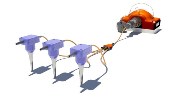
Figure 1. Three-Channel Digital Seismic Scout Station, equipped with GS-One seismic sensors.
Data acquisition system. Antenna consists of seismic sensors (antenna aperture approximately amounts to 1000 meters), sensors shall be penetrated to the depth of 1-2 meters depending on the geological conditions. Distinguishing features of the observation method (Fig. 2) consist in high mobility, fast deployment, high resolution, low cost of receipt, transfer, and processing of microseismic data. The distance between the sensors should be about 50 meters.
Typical sizes of array are of the order of 1000х1000 meters. The number of vertical sensors is 400. For time sampling of signal equal to 0.5 ms, the depth of monitoring can be from 700 to 5000 meters.
The array will be able to monitor the MSHF in 7 parallel horizontal wells with a length of 1 km and located at a distance of about 300 meters from each other (Fig.2.)
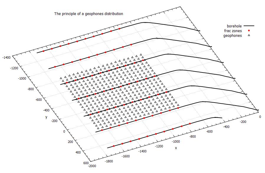
Figure 2. Data acquisition system
Tasks solved upon passive monitoring:
- Monitoring of the displacement front.
- Determination of the active bore hole zones
- Detection of the fault block structure near the bore hole bottom
- Monitoring of the filtration activity in the bore hole vicinity after monitoring of fracturing treatment
Monitoring of the displacement front. Determination of microseismic event hypocenters allows to monitor displacement front of the liquid from the space near the bore hole by means of a working agent. In case when the displacement process has just started, dynamics of the seismic activity distribution can be observed in time (Figure 3), and the direction of the front expansion can be determined.
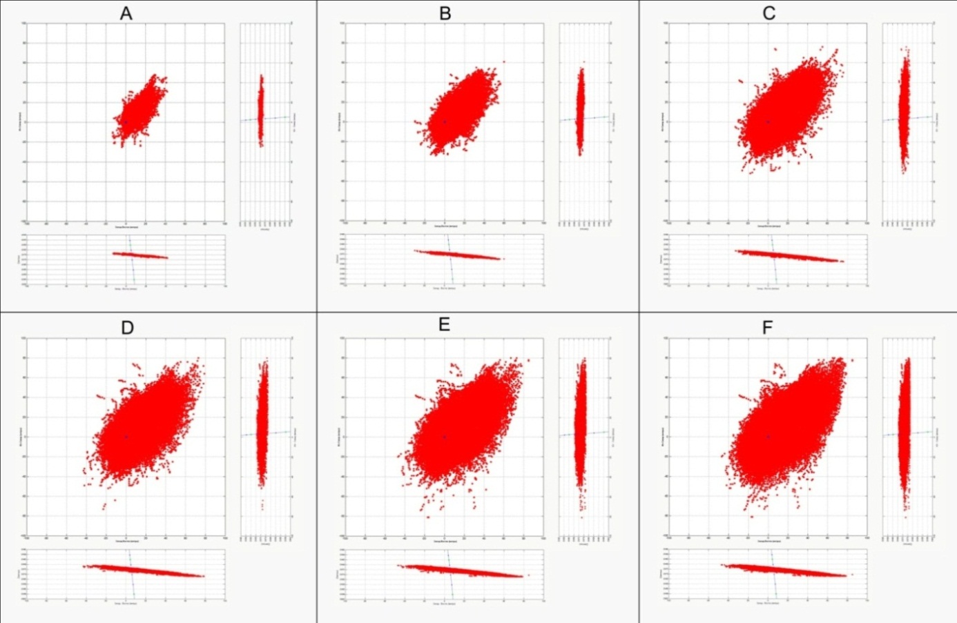
Figure 3. Frames of development of the microseismic activity cloud, consistently in a 100-Hour Interval, grid size 10 meters
Based on the solution of the inverse amplitude problem, seismic moment tensor has been obtained. It allowed to determine energetic parameters of the microseismic events which, in their turn, characterize the microseismic activity processes upon pumping down of liquid into injection wells. Based on the analysis of the microseismic activity zones within time (Figure 4), assessment of the movement direction of the pumped down water (flood front) has been performed. The microseismic events registered within 15 days of observation are presented in Figure 5.
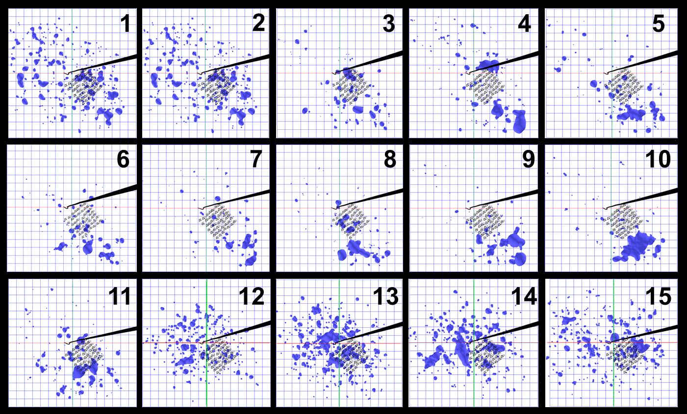
Figure 4. Isosurface of the energy density of the microseismic events registered in the zone of the injection well of the hydrocarbon deposit projected onto the daylight surface; grid size 100 m; isosurface contains 98% of the microseismic emission energy; red line denotes a seismic fault, black line – vertical bore hole
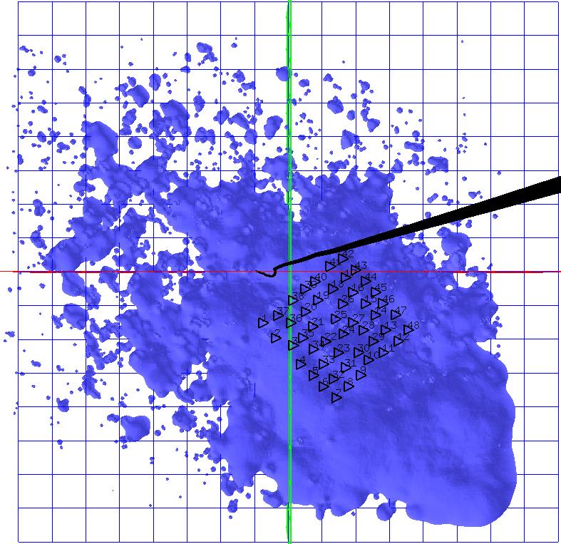
Figure 5. Isosurface of the energy density of the microseismic events registered in the zone of the injection well of the hydrocarbon deposit within 15 days of observation projected onto the daylight surface; grid size 100 m; isosurface contains 98% of the microseismic emission energy; black line – vertical bore hole
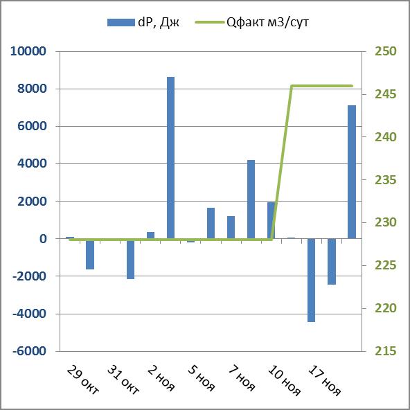
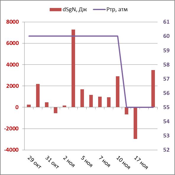
At figure 6, histograms of the non-compensated part of the deformation energy of isotrope extension (dP) and maximal adhesion tensions (dSgN) are presented in combination with daily pumping down volume and pressure charts. Reduction of pressure and increase of pumping down volume are reflected by energetic parameters.
a
b
Figure 6. а) histogram of the non-compensated part of the isotrope extension deformation energy (blue) and liquid pumping down volume chart (green), b) histogram of the non-compensated part of the maximal adhesion tensions (red) and pipeline pressure chart (violate)
Determination of the active bore hole zones. Drainage area of producing wells at the hydrocarbon deposit is a source of the useful and important information. The highlighted zone in Figure 7 is the zone of the greatest microseismic event intensity at the deposit in course of production in the porous reservoir without pressurization (“for exhaustion”).
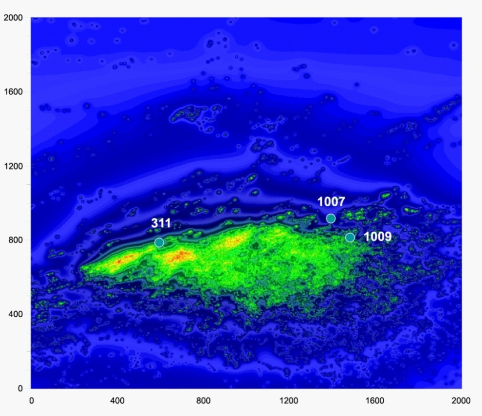
Figure 7. Determination of the drainage zone of producing wells, warm color corresponds to greater intensity
Detection of the fault block structure. In Figure 8, results of microseismic monitoring of hydrocarbon production “for exhaustion” in the mixed type reservoir. The fault block structure near the producing well is characterized by the previously performed monitoring of fracturing treatment
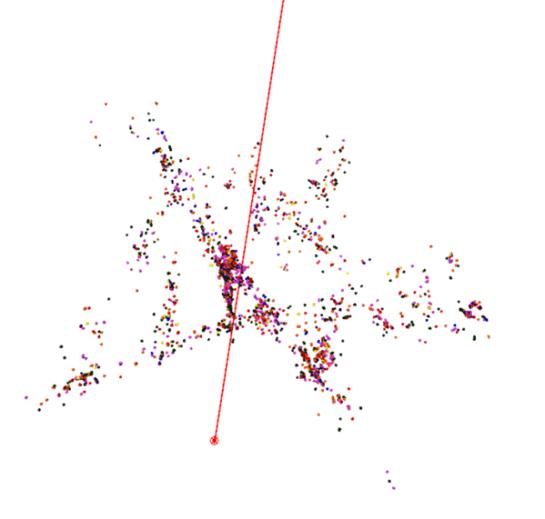
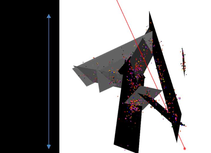
Figure 8. Microseismic events forming the fault block structure near the vertical producing well; red line – well-bore trajectory.
Monitoring of filtration activity. Presently, methods of production in the hozinontal wells with the use of multistage hydraulic fracturing (MHF) have been widely applied. Traditionally, microseismic monitoring is applied to control over MHF, however, such application does not provide information on the quality of work of separate ports. Passive microseismic monitoring performed after MHF (Figure 9-10) allows to record microseismic activities near producing ports. Results of surveying the influxes in the well showed that only the last 3 ports near which microseismic activity is observed have a well performance.
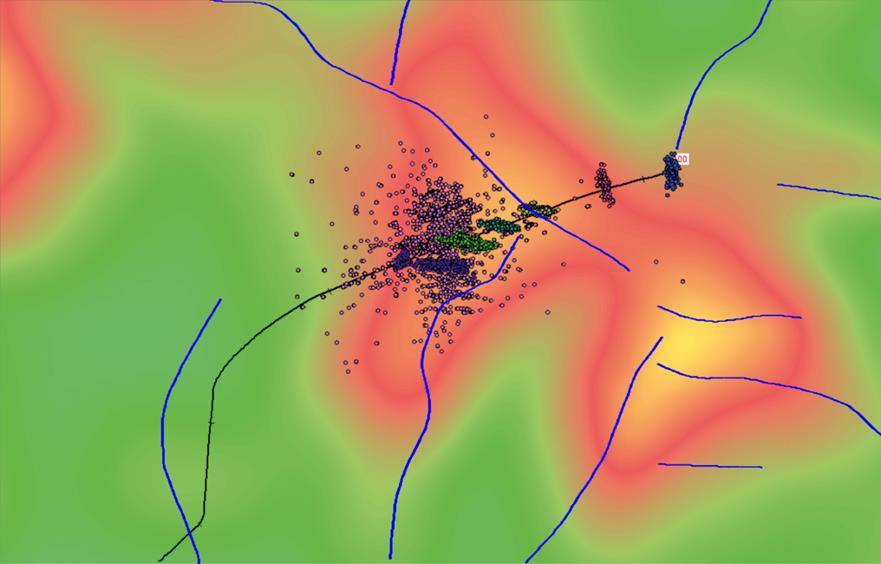
Figure 9. Structural chart with plotted faults and microseismic events, registered in course of MSHF and passive monitoring (lilac). Bazhen formation.
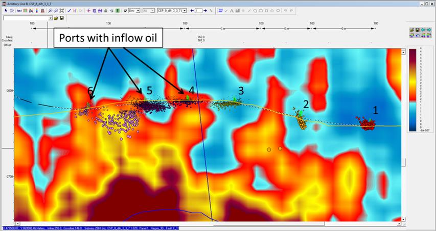
Figure 10. Vertical slice of the cube of scattered waves along the profile line passing trough the horizontal well. Bazhen formation.
The method LT-MSPRM used since 2002. Tested on 85 oil fields.
PDF Version: