
The Common Scattering Point Dip method
A considerable fraction of global oil and gas resources is accumulated in fractured reservoirs. These reservoirs are widely spread in many oil- and gas-producing regions including the Near East, Middle East, Northern Caucasia, Caspian Sea region, Siberia, Iran, Iraq, Saudi Arabia and others. Deposits in fractured reservoirs can be classified as complex structure deposits. The reason is the more complicated distribution of oil in fractured reservoirs than in porous-type reservoirs. Oil migration and accumulation in such reservoirs is controlled by the fractured zones. The configuration of reflecting horizons as the result of conventional processing of seismic data is not sufficient for the study of fractured reservoirs. Fracture zones do not form seismic reflections, but instead are the sources of scattered (diffracted) waves. The amplitude of scattered waves is 1-2 orders lower than that of reflected waves, which are intense undesirable waves in the study of fractured reservoirs. That’s why fractured reservoirs usually are missed.
The Common Scattering Point Dip method is an original pre-stack migration method for seismic data processing. This method provides a forecast of fractured reservoirs from the scattered waves separated out from the full wave field, as well as porous reservoirs from the reflected waves. This method follows a strict solution of the inverse problem, aimed at separation of the scattered and reflected components from the full wave field. Mathematically correct wave separation provides the opportunity to visualize the scattering elements usually invisible in conventional seismic data processing.
The CSPD-PSTM software provides diffractor time sections (or cubes for 3D) containing only the images of the geological scattering elements (CSPD-diffractors) and reflector time sections (or cubes) without these scattering elements (CSPD-reflectors). CSPD-diffractor sections (or cubes) contain unique information on fractured zones. Such information is totally lost in conventional seismic data processing against the background of more intense reflecting elements. In addition, the CSPD-reflector quality is higher than in conventional processing thanks to exclusion of scattered waves from the reflector time section (or cubes) as undesirable.
Technology based on the CSPD-PSTM software has the form of completed workflow of 2D/3D seismic data processing and interpretation. Figure 1 presents comparative diagrams of 3D seismic data processing with the use of the conventional method and the CSPD method. Figure 2 gives comparative diagrams of the CSPD workflow of conventional seismic data processing and interpretation based on reflected (left) and scattered (right) waves. CSPD-diffractor and CSPD-reflector cubes contain reciprocally complementary information on the investigated geological medium. This takes into account the complete graphic representation of seismic data processing, so that interpretation by the CSPD technology has two branches. The left branch and the right branch in figure 2 provide porous and fractured reservoir modeling respectively.
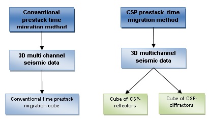
Figure 1. Diagrams of 3D seismic data processing: conventional method (left); CSPD method (right).
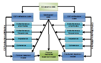
Figure 2. CSPD seismic data processing and interpretation workflow. CSPD-reflector cube provides porous reservoir model (left), CSPD-diffractor cube provides fractured reservoir model (right).
The CSPDmethod is marked by high resolution. Figure 3 presents an anticline flexure model used for synthetic seismic data calculation. The model consists of three layers. The intermediate layer, 50 m thick, contains circular inclusions with diameter of 40 m. Synthetic modeling demonstrates that the amplitudes of the inclusion scattered waves are from 50 (left inclusion) to 250 (right inclusion) times lower than the amplitudes of the reflected waves. The time section obtained with the use of the conventional time pre-stack migration method (middle of the image) shows only the reflecting interface, while the scattering elements cannot be seen, whereas the inclusions are distinctly visible in the section obtained with the use of the CSP method (bottom of the image).
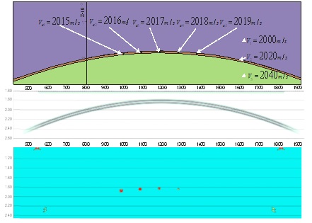
Figure 3. CSPD method resolution in the anticlinal fold model. With CSPD, inclusions that are missed with conventional processing are easily resolved.
The bottom line
The CSPD method dramatically changes the approach to resource estimation both in newly investigated and developed oilfields.
The CSPD method is highly efficient in detecting fractured reservoirs by use of scattered waves. The method has an excellent potential for detection of minor acoustic inhomogeneities in deep horizons. The CSPD method follows a strict solution of the inverse problem aimed at separation of the scattered and reflected components out from the complete seismic wave field. The accuracy of fractured reservoir forecasting exceeds 80% based on the results of data processing conducted for 20,000 kilometers of 2D seismic lines and more than 5000 square kilometers for 3D seismic exploration.
For further information see CSPD